Direct Drive has seen a re-birth in awareness and new applications over the past 20 years. Driving a shaft directly is really nothing new and has been done for over 100 years. What has changed is the types of motors used for the application and types of motor controllers that are available.
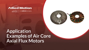
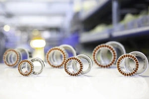
The most widely used motor type for a direct drive application is typically a high pole count permanent magnet synchronous motor, (A.K.A. Brushless DC), that has a large diameter and short axial length. Its magnetic and mechanical configuration provides high torque and a high ratio of electrical drive frequency to mechanical speed. Many of these motors also have a large through hole for feeding wires and optics through the center of the assembly. Motor controllers with high-speed processing power can control motors down to zero speed with full torque output as well as controlling torque over a wide speed range along with acceleration and velocity profiles. Given the correct electrical configuration and control scheme, direct drive applications can be at high speeds greater than 50krpm, (for example, a direct drive machine tool spindle), or low near zero speeds, (for example, a satellite tracking gimbal system).

DIRECT DRIVE MOTORS
While many suppliers tout their “Direct Drive Motors”, Direct Drive is not a motor type, it is a method of connecting a motor to its load. It also implies that the speed and torque range is something usable without any gearbox or speed reduction present. Over the years trade names and phrases have been adopted that imply that a function is also form which is simply not true. Other familiar terms like this are AC Servo Motor, Stepping Motor, and Servo Motor. All these terms relate to how the motor is used or controlled, none of them reveal anything remotely true about the motor.
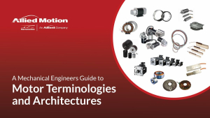
TYPES OF MOTOR
The accurate definition of a motor has to do with its mechanism for generating torque or force and how many electromagnetic phases it has and how they are controlled/commutated. Electromagnetic (EM) torque/force production is derived from an interaction between two magnetic fields or through a change in reluctance or permeance with position/angle, (or some combination of these two main groups). There are four main electromagnetic motor types in use today; brush commutated DC or AC motors, electronically commutated Synchronous Permanent Magnet Motors (AKA Brushless DC), AC Induction Motors (AKA Asynchronous), and electronically commutated Variable Reluctance (AKA Switched Reluctance). Of course, there are hybrid combinations of these technologies also in use. There aren’t any new forms of EM torque generation, in spite of what you may read on the internet.
Any one of the motor types above could be configured/optimized and controlled for a Direct Drive application. Since direct drive has been a thing for years, it is really direct drive optimized for low speed which is the new variant. It is a case where speed is low and torque required is high. The system may not be moving at all and just holding with direct torque control. This is where the ratio of electrical drive frequency and mechanical speed come into play, (A.K.A the electromagnetic gear ratio). The electrical input frequency is the rate at which the current is varied in the motor phases as the motor is commutated (either mechanically as in a brushed motor with commutator, or electrically via a controller and position sensor). The mechanical speed output is directly related to the electrical drive frequency and the motor pole count. Motor efficiency is driven solely by the electrical frequency and is not related to the mechanical rotation speed, (assuming you neglect bearing friction and other losses that are usually very small). A higher pole count motor will reach its peak efficiency at a lower mechanical rotation speed than a low pole count motor.
In conclusion, there is no such thing as a Direct Drive Motor, only a motor that is used or may be optimized to be used in a Direct Drive application. Direct Drive is a thing, Direct Drive Motor is not a thing. In fact, there are many applications where a motor that is typically optimize for direct drive is mated to precision gearing resulting in a highly compact gearmotor with a lower axially profile.

Thomas Edison

George Westinghouse
The AC power grid
The AC power grid has one operating frequency, 60 hz (or 50 hz in many parts of the world). AC Induction motors, (AKA Asynchronous motors), run directly from the AC power grid. The most common AC Induction motor today runs at a theoretical 1800 rpm and an actual 1750, when the rated torque load is applied. This speed is reasonably good for efficiency and provides a good ratio between size and HP rating. A fixed speed made for an easy calculation of power. The Horsepower standard was set in US to define motor frame sizes and was an indicator of torque output. Torque multiplied by speed, (in the correct units) results in power. A 1 HP motor is one that produces 36 lb-in of torque at 1750 RPM, a 2 HP motor produces 72 lb-in. That all works nicely until variable speed comes onto the scene, more on that later. Of course, the rest of the world used Watts, 746 of which equals 1 HP.
Pumping Systems & Speed Reducers
For pumping systems, 1700-1800 rpm is a good speed for power, size and efficiency, and pumps prevail today with this speed, i.e. a pool pump, or any household HVAC systems, and pumping systems for wells and water handling. Unfortunately, during the initial industrial revolution, 1800 rpm was too fast for most mechanical things in a factory and speed reduction was needed. Practical speeds like 50-250 rpm for big machinery and ranges from 10 rpm to 1000 rpm were typical in many different applications. Speed reduction could take the form of a belt and pulley system, or a mechanical gear reduction (yielding a higher ratio).

Speed reducers yielded a very positive secondary result, they also multiplied the torque output generally proportional to the ratio. If you needed 170-180 rpm, you could use a 10:1 speed reducer, the added benefit was a 10X multiple of torque minus any efficiency lost in the gearing system. Suddenly, customers could have all different speed outputs and torque multiplication. Things were not changeable on the fly, but with belt systems and pulleys speeds could be varied for different needs. Consider a milling machine or lathe from the mid 1900’s with speed adjustments via pulleys and belt changes. A speed reduction system is really a form of power conversion trading off speed for torque while maintaining the same power output, (minus efficiency, of course). Mechanical forms of speed reduction and torque multiplication became the backbone of the technology revolution. This all happened because the power source had a fixed frequency.
Microprocessors and transistors
Microprocessors and transistors then changed the course of history once again in the mid 1900’s. The factory requirements for setup configurations and change overs started to drive a requirement for variable speed, or adjustable speed by the press of button instead of a belt or speed reducer change-over. Motor drivers came on the scene that could convert the AC power to DC, then re-create AC power at different frequencies. They used a microcontroller/microprocessors to switch transistors and control the voltage, current and frequency. Suddenly, AC Induction motors could be run at all different speeds based on the Motor Driver, which was initially referred to as an Inverter because of its function of creating AC from DC.
Meanwhile, DC motors (brushed type) could already run at different speeds in the 1800’s. If DC power could have been localized to factories, DC motors would have been able to handle all of the different speeds. Of course, gear reduction for use in torque multiplication would still have allow much smaller motors to be used for slower speed applications where torque required was high and speed was low.

The War on Currents
The ironic thing about DC is that from the beginning DC current would have allowed better lighting, and variable speed from the start. At the same time the “War on Currents” was happening, the birth of the automobile was happening. More than 50% of the initial motorized buggies were powered by DC motors and batteries. When DC went away as a power source and battery technology evolution was not fast enough, AC became the standard, and the Internal Combustion engine prevailed, until recently. The world has come full circle 120 years later with electric vehicles operating from batteries once again. Some of the electric vehicles even use AC Induction motors with Inverters, but most are using a synchronous motor type that combines permanent magnet and variable reluctance torque production offering the highest overall efficiency throughout the wide speed range.
DC Lightbulbs
The world has also moved to LED lighting, which is inherently a DC light bulb technology. This lighting technology is significantly more efficient and uses less electricity. Solar panels produce DC current and batteries are used to store energy created by all renewable sources. Most generators today produce DC voltage the in turn needs to be converted back to AC to feed to the grid.
It is possible that the correct answer in the late 1800’s was to use AC power transmission for safety and to cover long distances and use DC technology for light bulbs and localized factory motion with variable speed and to generate electrical with DC.
ADVANTAGES OF DIRECT DRIVE
There are several advantages to Direct Drive when used in precision motion systems. All transmissions, with a few exceptions, have efficiency losses, and backlash, and mechanical wear that limits life. The reliability of a motor system is inversely proportional to the amount mechanical things that are in contact. Adding a speed reducer/gearbox can multiply torque but is ultimately the limiting factor on life.
Direct Drive requires a much more intelligent higher bandwidth control system in applications where the loading and inertia change with position, like a robot arm. Control systems with the latest DSP and Microcontroller technology are much more capable of new more complex number crunching control methods. They can calculate a complete model of the motion system every few microseconds. This reduces the main handling changes in inertia with position. Gearing can help this by reducing the reflected inertia to the servo system by the square of the gear ratio but usually results in backlash, higher fictions, lower efficiency, and reduced life.
Gearing can multiply torque and reduce the reflected inertia to the motor which is generally a good thing in factory automation if you don’t need high speeds. However, there are some very complicating circumstances that arise when a highly geared system runs into a mechanical stop. All the benefits of low reflected inertia come back in a hurry to potentially damage the mechanical parts due to the stored kinetic energy. This is very true in the world of collaborative robots. It is common to highly gear robot joints to make them small. There are a handful of gearing solutions with zero backlash allowing this to happen (while they only last 10,000 hours at best). If a collaborative robot runs into a human and needs to stop for safety, having a high ratio gear can limit its ability to be safe. Direct Drive is a much preferred approach to collaborative robots because there is no torque multiplication and stopping is as easy as moving.
For high speed systems like spindles, direct drive is common. In this case it is not high torque, but rather high speed that is required. In some cases up to 100,000 rpm. AC induction motors are good for this application as long as the control system can operate the motor correctly at these speeds in the field weakening range.