Why is Km so important for robotics applications?

For certain applications, a motor’s Km is critical to defining motor output for the amount of heat generated. These applications are robotic joints, gimbals, fine positioning systems, and low voltage applications. Km is not as useful in power transmission applications that are constantly running at higher motor speeds in the 1000-10,000 rpm range.
What is Km?
- It is a figure of merit that can be calculated
- Km = Kt/sqrt(R)
- Ke = Torque Constant, NM/amp
- R = Resistance, Ohms
- Assumptions when using Km
- All heat is from copper losses due to current in the motor winding
- The units are correct, for example if Kt is NM/amprms then R needs to be the three phase equivalent of resistance, not the measured line-line value
- Km does not change with winding changes
- A motor can have any torque constant by scaling the winding, but its Km doesn’t change unless there is a physical change in the copper fill or motor size
- It is routine for suppliers to offer different windings for different speed operating points. The number of turns on a motor should not change Km
- Motor Km increase with diameter faster than with length
- Short fat motors will have higher Km than long thin motors
- Increasing diameter increases torque and cross-section copper area
- Increasing length only increases torque
- Km/Weight is a good figure of merit for a robot joint
- Km/Volume is ok if size is more important than weight
- Km/Rt is the most important for Robotic applications
When is Km not useful as a comparison?
- When motor speed is high core losses (hysteresis and eddy currents) can cause torque drag and heat. Km doesn’t account for this. High speed 1000-10krpm, for example.
- In a high acceleration application where system inertia is low. Km does not indicate a motor’s torque/inertia ratio. Km/Inertia might be a good figure of merit for that.
- If there is a mismatch between the motor driver and motor causing excessive heating or poor performance. Km will not help you out of this situation.
Sizing with motor Km
Selecting a motor based on Km is especially important if you have a tight thermal budget. In applications where the surrounding mechanical parts cannot get as hot as the motor itself, for example, specialty machines that need to be in a controlled temperature environment, surgical robots with humans local, collaborative robots next to humans, etc.
The most challenging motor applications in these areas, require that designers look at thermal modeling and some thermal testing to identify how much heat can be comfortably absorbed into the system. Typically, thermal resistance can be calculated/tested and then used to limit the heat power.
If your robot can only comfortably dissipate 30 watts of heat before the surface temperature exceeds the design limit you can use this information to find allowable Km.
Km = Torque required/SQRT(Power dissipated)
For example, if you need 1 NM of torque and can only dissipate 30 watts, then you need a motor with minimum Km = 0.18 NM/watt1/2. This motor would also have to fit into the space available and operate from your power source at the speed intended.
Km is a quick way to search for what you need. It can certainly identify when your requirements are not attainable. It may indicate that active cooling may be necessary if the size is small and the Km is higher than what is available.
Never use Km published in a motor datasheet. Always calculate it using Kt and R, which are always in the datasheet (and are also measurable parameters). Keep the units correct. For example, if Resistance is Line-Line measure (typical for a 3 phase motor), then it is required that you use a Kt that is a line-line value.
Km is very useful in comparing multiple motors of the same size. If size and basic parameters are available a quick comparison is easy. Be careful to factor in things like operating speed, inertia and electrical compatibility.
Using Km reduces the motor selection problem down to something basic. Every application also has electrical, thermal, and environmental challenges that must also be overcome. Knowing that you have the best available motor that meets your commercial needs can easily be accomplished with a Km comparison. Then you can address all the other challenges.
One last thing. Permanent magnet brushless motors (a.k.a BLDC or Synchronous) should never be selected based on the voltage rating. There is nothing magic about a 24 volt motor or a 48 volt motor. Look at the motor speed rating compared the speed you are operating at. A motor should be able to reach a speed that is 25% higher than you need at the voltage you will apply. If it can go 2-3X faster than you need, you have the wrong motor that will draw more current and could have excessive heating from PWM current ripple.
Km and low voltage applications
Another not widely used method is to look at Km when faced with a low voltage moderate speed (1000-5000 rpm) application. If two similar sized motors are compared to run at 24 volts and 5000 rpm. The motor with the higher Km will achieve higher efficiency and higher peak torque. This is due to the voltage drop across the resistance of the motor and assume that speed induced core losses are the same on both motors.
Watch out for motor ratings that vary with temperature
Internal temperature is a key requirement when a motor is designed. The temperature rating impacts selection of the magnet, the wire, the insulation system, bearings and overall mechanical design. This one parameter touches just above everything in the motor. Motor manufacturers routinely select a maximum temperature and work back from there. Underwriters Laboratories (UL) and other safety organizations have historically rated electrical materials based on temperature. A UL Class B rating is 130C, for example. If Class B is selected for operation, then electrical materials should be rated at above 130 degree C.
Most magnets have a reversable temperature coefficient between 1 and 10%/100 deg C. This means a magnet rated at 25 C may lose 10% of its strength at 125 C then return to full strength after cooling. There is also an irreversible temperature coefficient. For example, if the magnet above reaches 150 C (above the reversable temperature limit) then it may permanently lose 25 % of its value after cooling. If the magnet is internal to other materials that get hot it may see hot motor temperatures due to its environment. Some magnets are rotating on a shaft separated from the coil and can see much lower temperatures.
Internal temperature and external temperature are connected by the thermal resistance of all barriers between the heat source and the outside of the housing. Most motors that are fully assembled, (as opposed to frameless), have multiple internal components that impact how heat flows from the source to the outside. It is routine for manufacturers to mount the motor to a heat sink that emulates a possible application. Small motors tend to benefit greatly from this conduction into the mount, large motors have more surface area for convection and depend less on conduction to the mount.
Frameless motors are very popular today for advanced industrial and medical robotic applications. Designers highly integrate these motors in mechanical systems. This poses a more complex problem of designing for thermal requirements since the motor does not have a mounting surface and depends on the customer mechanical parts to be the housing.
Beware of motors that have internal electronic components. Most combination motors will carry a derating to minimize the impact on electronic components. Many of which can only handle 80 C. Power loss is generally related to copper heating, which is a function of the current squared. If a motor has a thermal resistance of 1 deg C/watt, going from 130 C down to 80 C would reduce allowable heating by 50 watts.
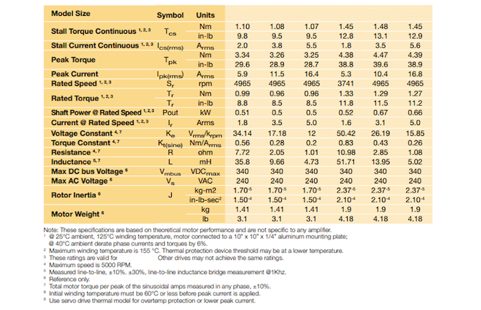
Below is a typical motor datasheet parameter table. The only measurable items are Voltage Constant, Resistance, Inductance, and Weight. The rest of the items are either calculations or inputs to the motor.
The notes below the table really identify the conditions used. It assumes that the motor is in 25 C ambient and asks for a derating if used in 40 C ambient. The maximum winding temperature is 155 C indicating class F insulation system. Torque output is based on these thermal conditions and a condition that motor is mounted to a 10 inch X 10 inch X .25 inch Aluminum plate. All measured parameters are +/- 10% and some are higher.
If you are going to use this motor in a medical device, like a robotic assisted surgery system. It will be in the operating room so 25 C is probably reasonable. The robot will not have a large aluminum plate. It has patient surface temperature limits in the low 40 C range, so the available temperature rise over ambient, (dictating the power that can be dissipated), is only 15 C.
Comparing the use conditions to the motor specification you will get the following;
- The motor ratings could vary 20%. To be safe derate the output to 90% to cover the low end of the specification.
- The motor datasheet assumes heat rise of 155C- 24C = 130 C above ambient. The application can only handle a 15 C rise on the surface of the robot.
- Assuming the internal motor temperature of the motor can be 50% higher than patent surface temperature (this is very generous, and needs to be tested), we can stretch the internal motor temperature to 30 C rise above ambient.
- 30C/130C = 23% of the datasheet heat rise. This might yield 46% of the rated torque but that must be derated to 42% of the datasheet value to account for parameter variation.
Datasheet information should be treated as a reference in most applications.

