Robot Joint Design for the New Designer
The new age of robotics and automation is here. The world can no longer rely on low cost labor, or low cost labor regions, to do mundane tasks. People have evolved intelligently to the point where it is easier to use new technologies for communication and social networking to get paid for their time, rather than to pick strawberries. Who will pick the strawberries?
During the 1st generation automation, (1980’s to year 2000), it was common to buy off the shelf components and couple them together to get things to move. Motors were mounted and coupled to shafts and smart motor controllers with microcontrollers (computers) inside ran these motors. The systems were better than the previous generation of industrialization, but lacked reliability, were generally hard to maintain, and not easily compatible with neighboring automation cells.
Today we have factory network systems, highly intelligent AI based software for monitoring BIG data, standards for communication, and yes… highly integrated robot solutions for moving things around and doing tasks (alone or collaboratively). Center to all robotic movements is a motorized robot joint. Except today, it is not the compilation of standard off the shelf parts, it is a uniquely designed highly integrated packaging for the right technology to create a seamless electromechanical solution.
A robot joint consists of a precision high ratio gear, a motor, and one or two encoders. Sometimes, there is a need for a fail-safe brake. Direct drive robots are entering for low payload, a subject for another blog.
How do you engineer a solution with all of these components? It is not exactly intuitive, but let’s give it a shot.
- Decide how fast you need move, how often, and how much weight you need to carry. This is easily calculated using Newton’s Law of motion.
- If there are multiple joints required, then the kinematic joints connecting each joint are used to break down the total needs into joint specific needs.
- Each joint will have a torque and speed required to overcome acceleration, friction, damping, and any potential loading (gravity, windage, or kinetic energy). Worst case loading is usually used to size each joint.
- Once the torque and speed are known, size must be considered. There is always a motor that can be used to directly drive the joint at required torque and speed, but it is usually way too large and heavy to use. This is where gearing comes to play. Using the gear will reduce the size of the motor quickly because mechanical gearing has a much higher torque density than a magnetic field can create.
- It is common to use mechanical gearing for high torque output or speed reduction. In the case of a robot, not just any mechanical gearing will do. Most gears have a thing called backlash, essentially disconnecting the input from the output under certain small angle movements. This can cause issues with hunting and control system tuning issues, especially if there is no encoder on the output. Enter Zero Backlash gearing, a must for robotic systems that are not direct drive (5kg payload and above).
- Ok, take the torque and divide it by a gear ratio of maybe 50-100 (the typical range for zero backlash gearing) and you get torque required for the motor. Be careful to navigate the speed increase associated with the gear reduction.
- Next look for a direct drive torque motor. Wait. Direct drive? The modern robot joint couples a zero backlash gear to a direct drive torque motor. It turns out that there is nothing direct drive specific about a torque motor which is just a high torque low profile motor. Today, most direct drive torque motors can run at 5000+ rpm with the proper electrical configuration and their size and weight are optimized. Inertia is higher than a normal motor, but in a robot high motor inertia is acceptable.
- Mount the motor to the gear using the gear’s bearing system, then add an absolute encoder. Absolute, really? Modern controllers will run the motor with a single absolute encoder eliminating the needs for separate hall devices or additional sensors. Absolute encoders are now in the price range equivalent to a motor with hall devices + and incremental encoder.
- Take time and effort to design the lowest profile package while still leaving room for wires, connectors, and safe distances for electrical safety.
- There are gears available today that have adaptors for motor mounting… don’t use them. Adding a complete motor via a flange and a flexible coupling to the gearbox, adds weight, reduces reliability and reduces performance. It also adds extra bearings, once again reducing life.
So, there are 10 steps to designing a robot joint. Below is an example of the finished product. A very high 50 NM/Kg usable output in a roughly 100mmX100mm package. Internal torque motor, internal absolute encoder. Very few parts. No couplings, no adaptors, no hall devices a total of nine wires, able to support reasonable axial, radial and moment loads.
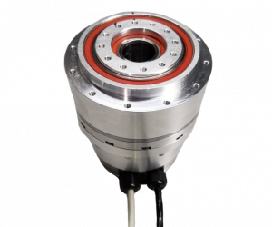
The SMRT-2000 is the first in a series of products from Sierramotion that has been designed and released as a preview to what is possible. It is also available in short lead time for testing and evaluation for future strawberry picking robots. Sierramotion will work with you to turn this product into the customized solution that works best in the project, environment, and power infrastructure available. Strawberries are not inside a factory, so IP65 sealing may be required. If the auto-picking cart is battery operated maybe 33.5 volts is required, not a problem, the electrical design can be changed to suit the need.